Forums
- Forums
- Duggy's Reference Hangar
- USAAF / USN Library
- Fleetwings BT-12.
Fleetwings BT-12.
Post a reply
- Go to Previous topic
- Go to Next topic
- Go to Welcome
- Go to Introduce Yourself
- Go to General Discussion
- Go to Screenshots, Images and Videos
- Go to Off topic
- Go to Works in Progress
- Go to Skinning Tips / Tutorials
- Go to Skin Requests
- Go to IJAAF Library
- Go to Luftwaffe Library
- Go to RAF Library
- Go to USAAF / USN Library
- Go to Misc Library
- Go to The Ops Room
- Go to Made in Germany
- Go to Campaigns and Missions
- Go to Works in Progress
- Go to Juri's Air-Raid Shelter
- Go to Campaigns and Missions
- Go to Works in Progress
- Go to Skinpacks
- Go to External Projects Discussion
- Go to Books & Resources
-
3 years agoSun Sep 19 2021, 01:04pmDuggy
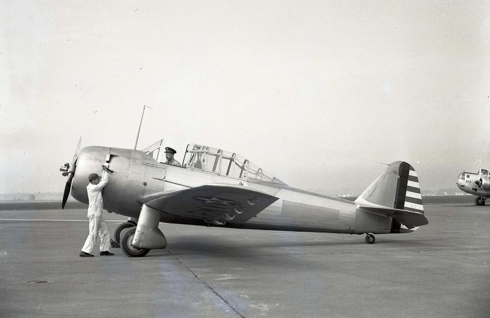
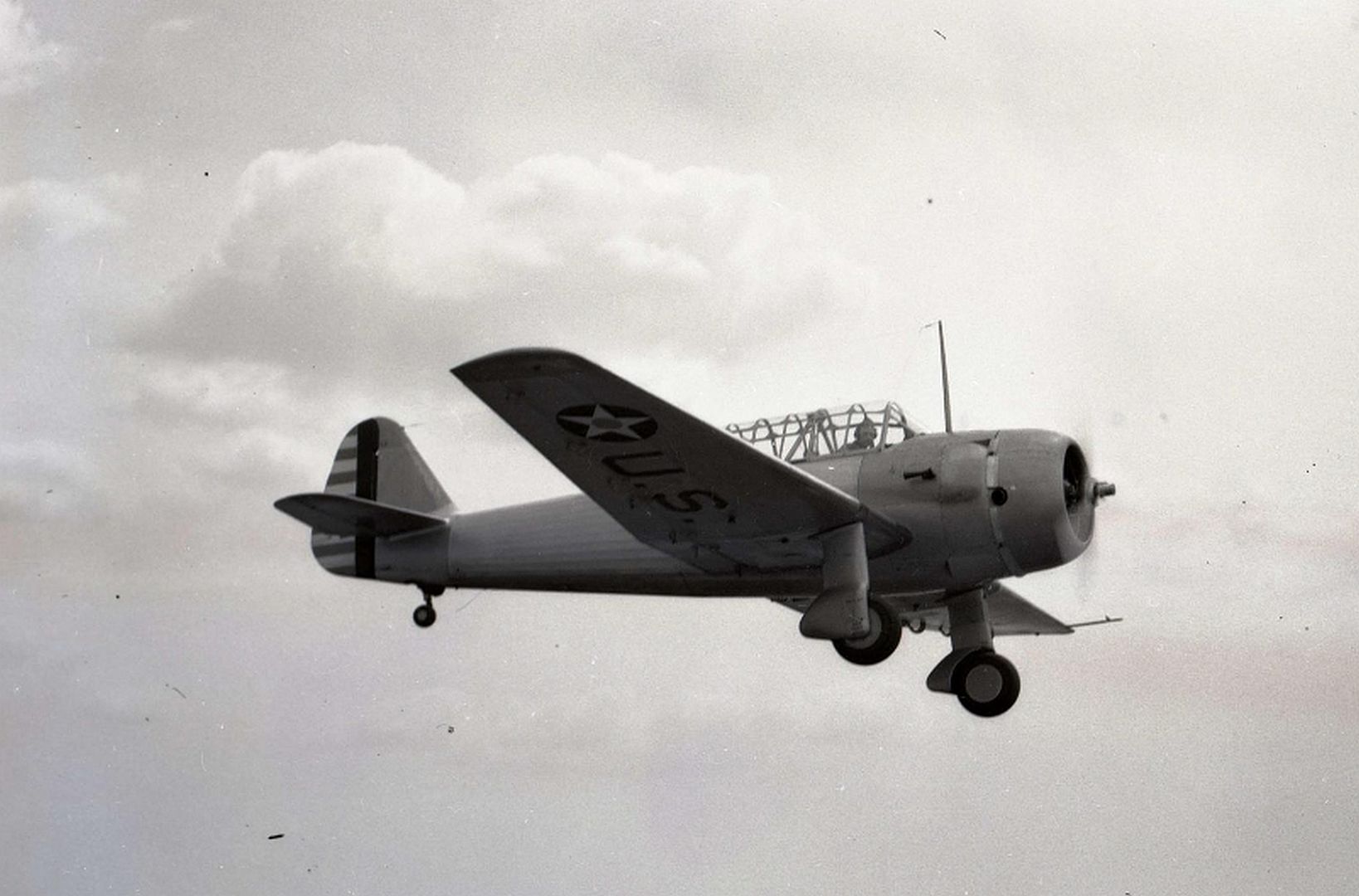
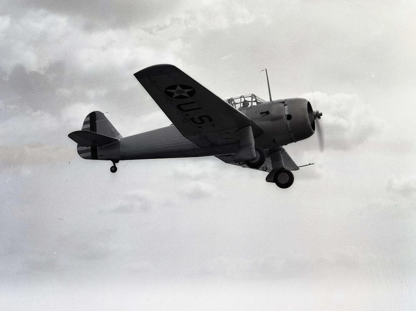
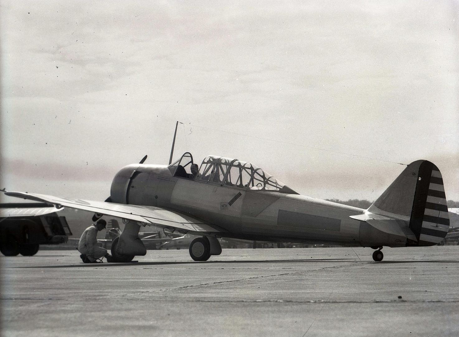
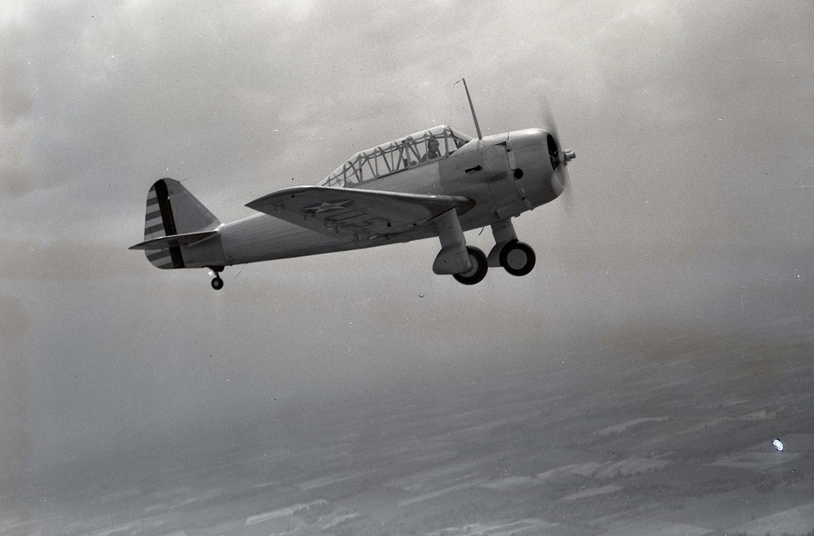
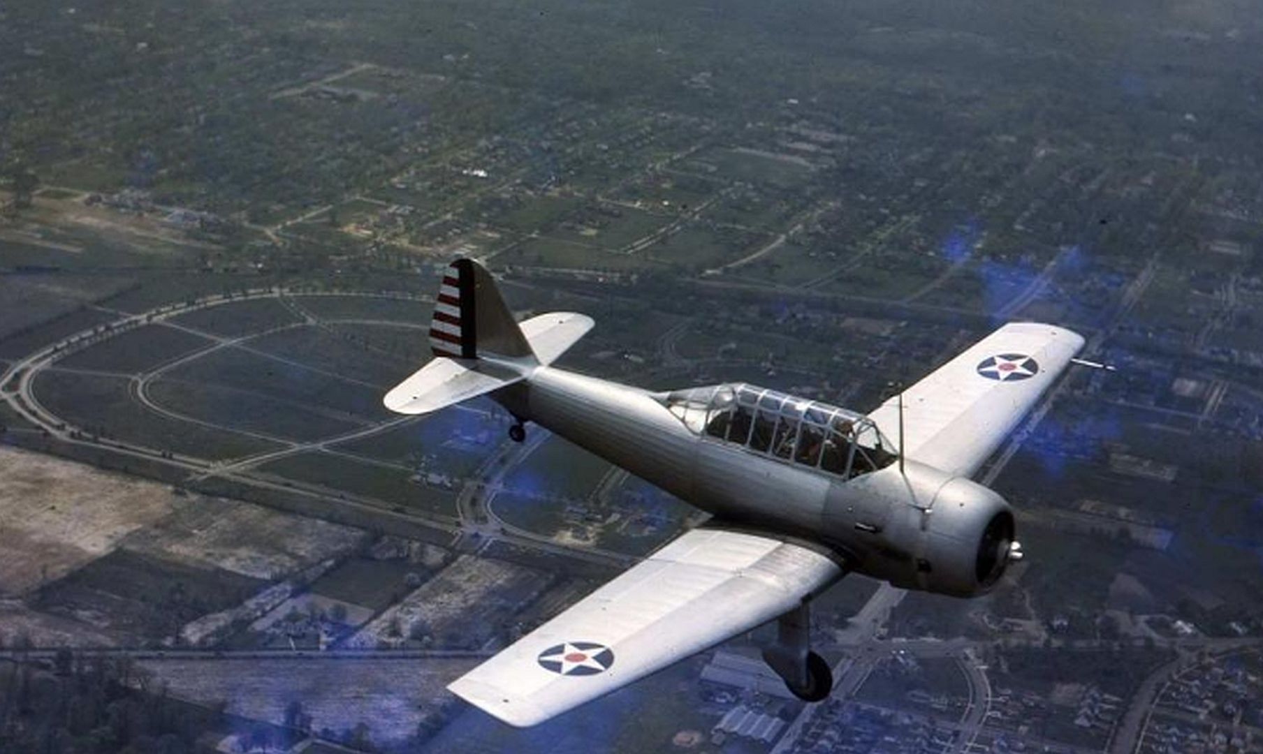
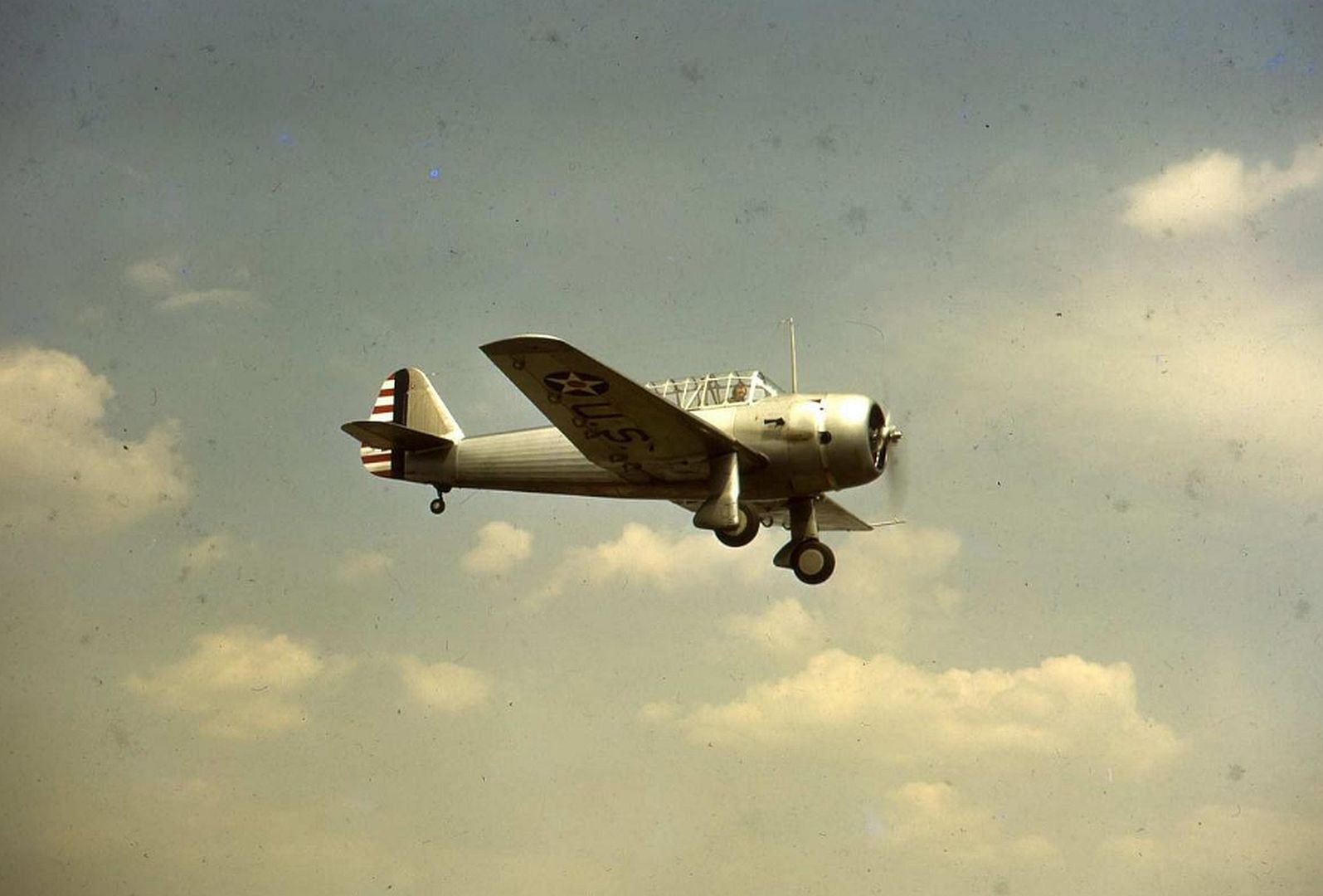
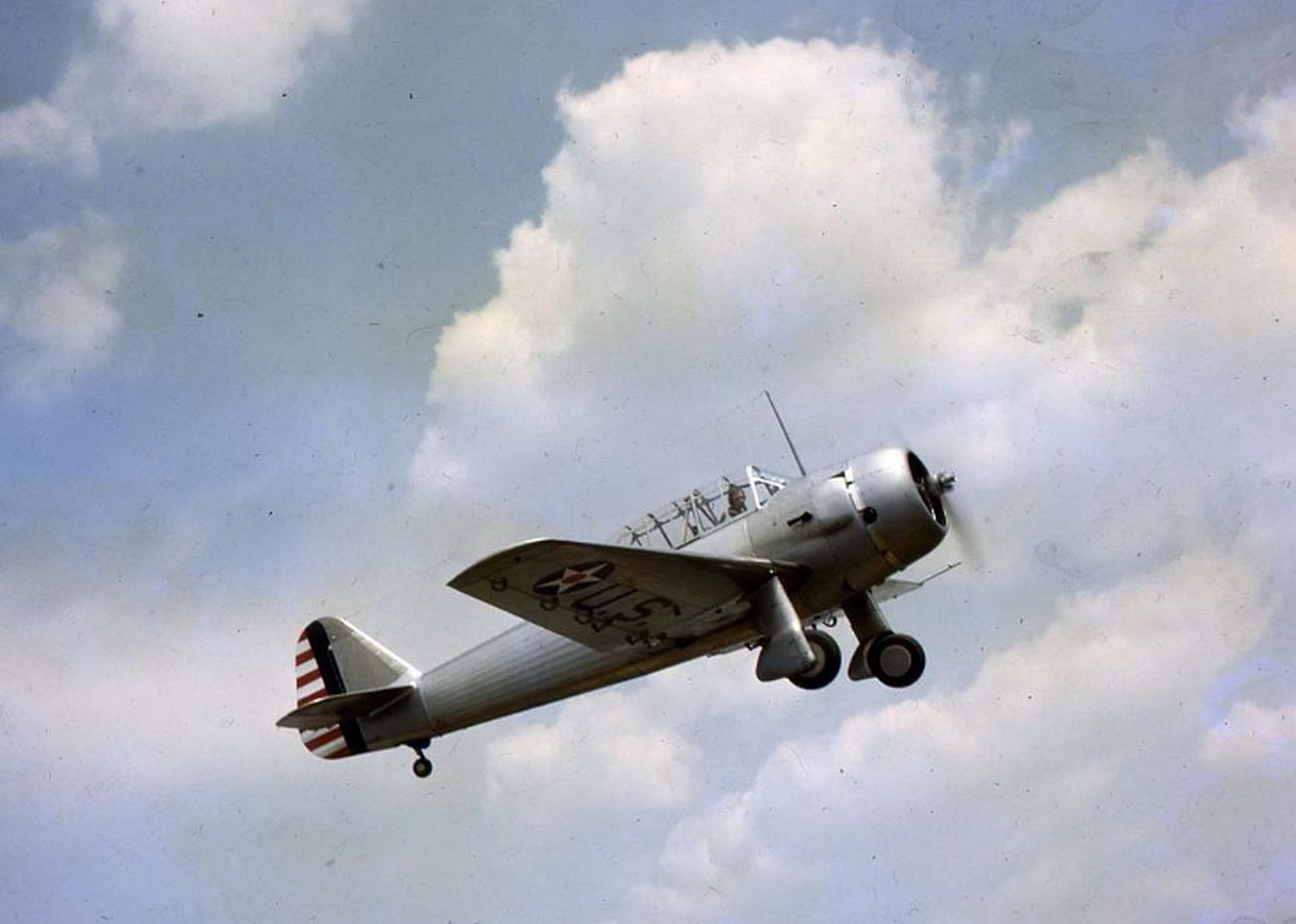
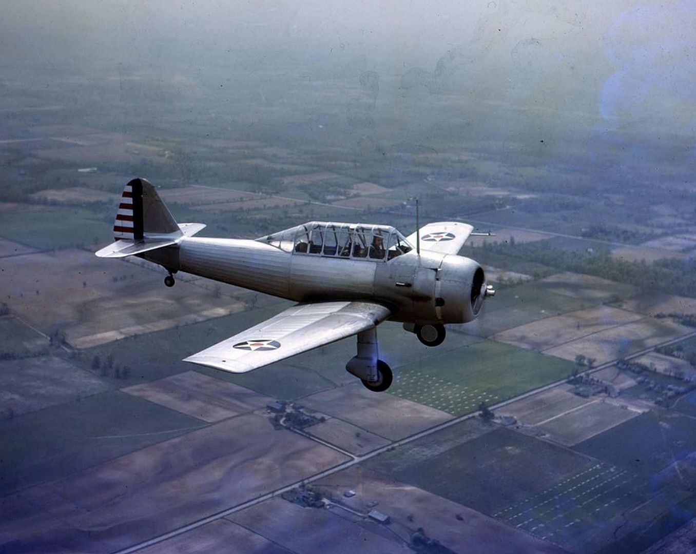
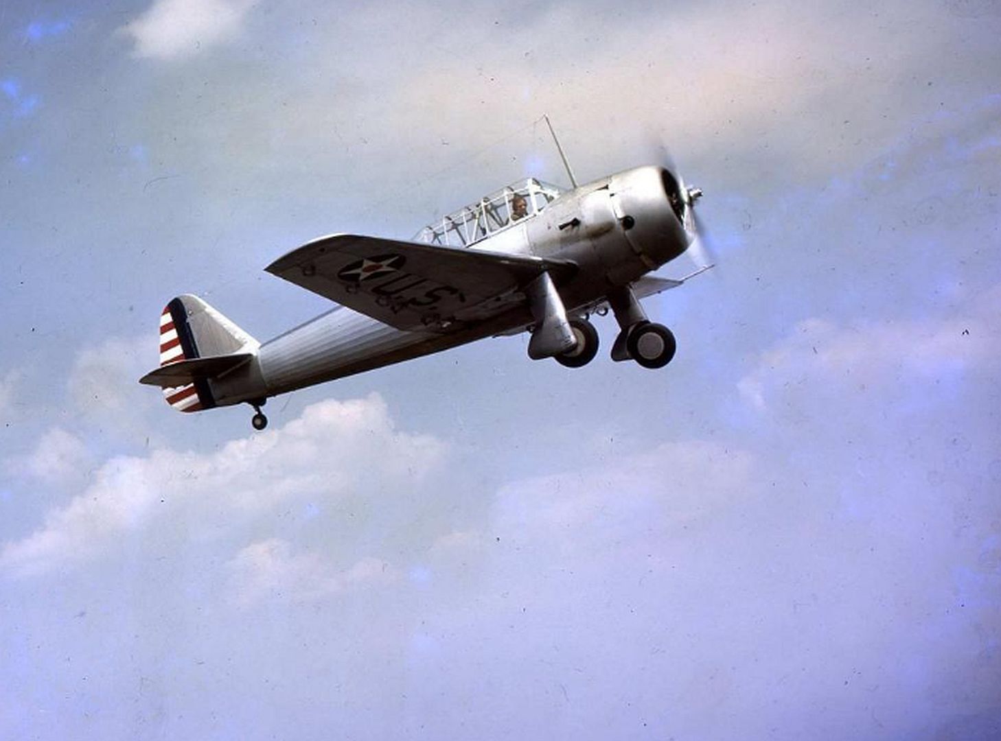
 Main AdminThe Fleetwings BT-12 Sophomore, also known by the company designation Model 23, was a 1940s all-metal basic training monoplane built by Fleetwings for the United States Army Air Forces. Only 24 production examples of the type were built before the contract was cancelled.
It was the first military aircraft to be constructed primarily from welded stainless steel.
Design and development
With the outbreak of the Second World War, the United States Army Air Corps (later U.S. Army Air Forces) was ill-prepared for a major war. In an effort to obtain as many aircraft as possible the USAAF contracted Fleetwings, a specialist fabricator of sheet stainless steel, to produce a basic training monoplane. A prototype Model 23 was ordered as the XBT-12 during 1939.
Design Analysis of the Fleetwings BT-12, this article was originally published in the October, 1943, issue of Aviation magazine, vol 42, no 10, pp 119-132, 356.By David Baker
Detailed study of America's only stainless steel airplane, a basic trainer built for arduous flying conditions and ease of maintenance.
In designing the Fleetwings BT-12 basic trainer, three main objectives dominated all decisions. The first called for a trainer which would retain all the desirable characteristics achieved in previous models of the type, but overcoming their observed weaknesses; the second demanded an airplane which would embody the utmost simplicity of maintenance; and third, a direct comparison on a standard production type of the familiar dural with a material little used throughout an entire airplane — stainless steel.
It is no commonplace job to design a basic trainer. The craft must be a moderately fast and a capable performer to serve as an intermediate step in pilot training. With two cockpits, the airplane must behave consistently with either one or both occupied. It must be inherently safe, yet still be suitable for certain maneuvers as a part of training. In other words, a basic trainer is expected to do all that a bad airplane will do when improperly handled, but do it safely.
This is as complicated a set of requirements as confronts any type. However, data compiled from observation and experience with many trainers at Wright Field pointed the way to some qualities to be striven for in a new design. Although to the casual eye the BT-12 may be just another trainer, fundamental changes have been incorporated which make this airplane advanced in its class and highly suited to its purpose.
In the first place, the engine has been brought back as close as space permits to the cockpit enclosure, and the sweepback greatly reduced, giving a much shorter range of shift in CG. locations. Contributing to this is the incorporation of an integral fuel tank in the wing center section directly under the fuselage. The shift in cg. position caused by a full or empty tank is negligible. Shortening of the fore section has also greatly improved pilot visibility.
The fuselage has been somewhat enlarged for better streamlining, the tail section slightly lengthened, tail surfaces enlarged, and the fin set farther forward. Considerable "wash-out" has been built into the wing (from +1.2° at root to -2° 23' at root of tip) to eliminate tip stall. As a result the stalling speed of the airplane is rather indefinite, depending on what is defined as stall. Stall warnings occur from 88 mph on down, with actual stall from 70 to 60 mph but the wing tips never stall out.
Although the original XBT-12 was designed for retractable landing gear, the classification of BTs and ATs was separated at that time, and the design had to conform with fixed gear. Even though the present model is without fairing on the landing gear, it is exceptionally fast for its type. The XBT had a top speed of 177 mph with fairing and the current model attains 168 mph without fairing, and cruises at 145 to 150, which is about the same as the AT class.
It is extremely maneuverable, yet requires the proper degree of precision from the student pilot to execute a maneuver perfectly. Control forces have been intentionally made moderately heavy, to simulate the larger plane characteristics to which the student is progressing. Spin characteristics are good, and conform exactly to the NACA reports on what the design should do. The airplane will recover in the required limits with rudder alone, or with stick and rudder. It will recover with the controls neutral, given a little more space, and the length of time it is kept in a spin does not diminish ease of recovery.
Maintenance Considerations
Due to the hard usage which is the lot of trainers and, equally, to the large numbers in which they are used, serviceability was set forth by the Army as an essential requirement. Planes and crews tied up in maintenance can slow up a training program as quickly as insufficient aircraft, therefore every effort was made to make this airplane easy to care for.
Some of the features in this direction have been described in these pages, most recently in Aviation Dec, 1942, but they are so numerous that they require fuller coverage.
Most extensive provisions for ease of access are the removable fairing panels which cover most of the fuselage. Execution of this idea begins at the nose of the airplane with the ring cowl, which is divided into four sections held in place by four joint strips, fastened by Shakeproof fasteners. Aft of the engine section, all fuselage side panels are removable, and are also held in place by Shakeproof fasteners. The entire airplane can be stripped of removable panels from engine to tail by one man in less than half an hour, giving quick access to frame, controls, and wiring.
Leading edge of the center wing section is also removable for quick inspection of landing gear attachment and fore part of integral fuel tank. Attachment is by means of Phillips screws, as are also the plywood wing tips to outer panels.
In line with this policy is the use of bolts wherever quick detachment is desired, and the diversity of sizes has been kept as close as possible — between AN3s and AN10s. Among points where bolt attachment is used are the following: Landing gear struts are fastened by four bolts each, fuselage to center section by six, fuselage monocoque to tube frame by four at each joint, stabilizer spar to fuselage by four, and fin to tail section by four. Another important application is in attachment of trailing rib sections to wing spars, where ribs are fastened top and bottom by small bolts. This means that only simple tools are required for replacement of these sections in the field.
The cockpit canopy is an easily removed and repaired unit, consisting of a 53ST Hunter Sash extruded aluminum frame welded together with gussets. The front windshield panel is a separately removable unit fastened by screws at top and lower front of frame at cowl. Lower corners are fastened to brackets on the longerons by bolts. Remainder of the canopy is composed of two sliding sections over the cockpits, fixed center and rear sections. Each sliding unit can be removed by taking off fairing around lower part of enclosure, aligning rollers on the track with access holes in the frame and removing roller bolts. The entire canopy can be removed by taking off all fairing and unfastening the whole track from the fuselage.
All the transparent panels are set in extruded rubber moldings and can be removed and replaced by hand. Windshield side and center panels are 3/16-in laminated safety glass, all others are 3/32-in plastic. Emergency exit is provided by means of "knock-out" panels front and rear at right side. Movable sections can be fixed at three positions between open and closed.
In the electrical system, circuit breakers have been concentrated in the main junction box located on the left side of the fuselage just above the leading edge of the center wing section. This unit is easily reached from the ground by merely removing the panel and cover. Use of conduit plugs wherever possible instead of solder connections has made installation or removal of individual units very simple and fast.
The tool compartment is also made quickly accessible from outside by means of a hinged panel in the plywood fuselage fairing on the left side behind the rear cockpit. It is opened by the same key which operates the canopy locks. A fire extinguisher is also at hand, accessible both from inside and outside, since it is mounted on a spring loaded door in the rear cockpit.
All control cable pulleys are packed and self-lubricating, requiring no attention after installation. The elevators, being of symmetrical air-foil section, have been made interchangeable. This requires a high degree of accuracy in locating and boring holes for the control attachments, but it halves replacement stocks.
Preparation for, and actual engine changing is made easy by adherence to simplified standardized engine connections and attachment of engine-to-mount and mount-to-fuselage by bolts.
Stainless Steel Construction
The third design objective — particulars of stainless steel construction and a comparison standard with the same type in dural — leads to the heart of the BT-12 design, for maintenance considerations are inseparably bound up with production methods, and the material used contributes greatly to the trouble-free qualities of the airplane.
Before considering each section in detail, it will be profitable to have in mind some comparisons between stainless and dural generally. In stainless steel, .018 gauge is about equivalent to 24ST (.040 gage), and steel spotwelds are stronger than 1/8 rivets in 24ST. In the matter of cost, 24ST comes to about $0.334 per lb, stainless to about $0.66 per lb. Yet such savings can be realized in manufacture, particularly by elimination of riveting, and finishes for detail parts and assemblies, that costs of finished articles delivered are generally lower on a production basis than in dural. This is based on experience with the BT-12, and with tail and control surfaces built for other planes. The reasons will be seen in detailed study of the BT-12.
Particularly interesting discoveries have been made in connection with the fuselage midsection. Where the XBT was wholly constructed of rectangular welded stainless truss framework, the present BT-12 has a chrome-moly tubular frame,and although the former is as much as 75 per cent cheaper in first cost, installation costs in this section have been boosted 300 to 400 percent. In addition, it is 18 lb heavier than the stainless frame.
Looking at it from a purely mechanical standpoint. a tubular framework presents the greatest difficulty to any sort of attachment, in direct contrast to straight sided members. Further obstacles are encountered in manufacture, where welding distortion with chrome-moly tubing — even with arc welding — renders a high degree of accuracy far more difficult and expensive to attain than with stainless steel.
In connection with welding chrome-moly, an interesting phenomenon has been observed by all users of this type of fuselage frame, and that is its effect on a magnetic compass, for chrome-moly is inherently magnetic. Use of arc welding, almost dictated by demands of accuracy and production time, further increases the tendency. Add to this the effects of Magnaflux for inspection — even with every attempt at demagnetization — and the result is 30 to 40° compass error and, in some cases, a completely "frozen" compass. The only recourse is to mount a remote reading compass in another part of the airplane, as was necessary in the BT-12 and many others. Since stainless steel "grade used here is 18 and 8" is austenitic and almost wholly non-magnetic, it allows perfect accuracy of compass within the frame.
In summary on stainless steel, it may be generally stated that wherever stress is concentrated, a structure of this material is usually superior due to its strength-weight ratio and freedom from corrosion deterioration. In manufacture, the ease with which it is welded without cleaning or preparation, simplicity of jigs in which hand tong welding can be accomplished, and the resultant infinite possibilities of subassembly application, more than compensate for a nearly-double first cost of material, which, after all, constitute only about 10 per cent of the finished airplane cost. Chief drawback in its use is the fact that it cannot be routed with present tools, due to its hardness.
Fuselage
Except for the chrome-moly tubular framework in the cockpit region, the fuselage is of spot welded stainless steel construction. Length without engine mount is 259.5 in, with mount, 283.26 in.
The firewall and angles are annealed and formed. Tensile strength of annealed stainless is about 80,000 lb; average forming operations bring it up to about quarter hard, or 125,000 lb. More severe forming raises it slightly higher. For slight forming operations the material is used half or quarter hard, for severe forming it is used full annealed. Parts which are not formed are full hard (185,000 lb) and this is used nearly everywhere throughout the plane.
Where the engine mount bolts to the fuselage and firewall, four conical aligning studs are provided to aid in matching the bolt holes. The tubular section is provided with six bolt holes for attachment to the center wing section.
In the aft monocoque structure bulkheads are rubber formed. Contrary to general belief, stainless is quite easily adaptable to this technique, and parts made in this manner include wing leading edge formers, bulkheads, and wing ribs in the D-spar section.
Upper and lower monocoque coverings are stressed-skin structural members. Except for bolt attachment to the tubular frame, this structure is spot welded throughout, the side truss framework being welded together as a unit in the jig. Vertical, diagonal, and horizontal members are "hat" sections made on the draw bench. The upper rear shear panel is annealed sheet, with welded-on pads to take the stabilizer spars. The tail post is also formed annealed. A shelf just aft of the tube structure forms the tool compartment floor. The lower rear covering, with tail wheel opening, is annealed stainless sheet formed under drop hammer. Covering of the fuselage is plywood except for the engine section and fairing under the center section from the engine accessory section aft to the monocoque. This is dural sheet, to better withstand ground abrasions and knocks, as well as accumulations of oil, dirt, gas, water, etc.
Center Wing Section
Most striking example of what has been done with stainless construction is use of the structural space in the torque box of the center wing section for an integral fuel tank which has proved one of the most successful of this type. First attempts at construction by spot welding and solder were not very successful, but the seam welding technique, which is actually a series of overlapping spot welds performed by roller electrodes, has effectively solved the problem. Tanks remain leakproof in use, and under Army vibration tests — except for some trouble with the aluminum sump attachment which was soon corrected — the tank outlasted the test table.
Skin and corrugation in fuel-tight bulkhead are seam-welded through flanges of front and rear spars. End bulkheads are seam welded through reinforcing plates to a U-shaped member on its side, which forms the joint between inner and outer reinforcing plates, bulkhead, and covering on each side of the bulkhead. The sump at bottom of the tank is an aluminum casting bolted into a formed stainless steel collar. Two stand pipes into the tank provide for main and reserve fuel supply. The filler neck is accessible through a hinged flap in the leading edge, which is itself removable for inspection of forward spar and tank.
Center trailing rib section is made to be easily removed or replaced, the ribs being bolted to the rear face of the rear spar. A walkway next to the fuselage is also built into the wing flap at this point. Covering of these ribs is by flush fitted fabric, fastened down into M-section capstrips by an 0.008 gauge stainless retaining strip over reinforcing tape secured by flat head sheet metal screws and covered by tape strips.
Outer Wing Panels
Outer wing panels are of stainless, D-section monospar construction with a flush fabric-covered trailing rib section aft of the spar. The outer panels are joined to the center section by stainless steel bars at top and bottom, fastened by 5/16-in screws and channel nuts. The web of the outer spar bolts to the the rear spar of the center section, and a reinforced vertical angle piece welded to the outer wing bolts to the web of the front center section spar, thus giving attachment around four sides of the center torque box. The joint is further strengthened by finger plates which underlie the attaching bars at top and bottom, and they are welded back to the corrugation for several inches. The stainless skin butts up flush, while to the rear, gap strips cover the joint.
Spar section ribs are rubber press-formed annealed stainless, reinforced at the flange caps by narrow strips of the same gage welded inside upper and lower flanges. Skin and corrugation are welded together before application by a rolling welder which spot welds the skin to two rows of the corrugation at a time.
Finished sheets of skin and corrugation are applied as a unit. Ribs are fastened to the corrugation by means of annealed stamped clips, which are first welded to the corrugation before application of the skin. Ribs fit into the clips and are welded in place. This method, used throughout the airplane, makes a strong, homogeneous structure.
Trailing edge ribs are built-up members and are connected at the rear by a false spar to distribute concentrated loads from hinge ribs to adjacent ribs, and to provide contour for fabric covering. Aileron hinge brackets are made up of two stainless plates, one of which is stamped into a hat section over which is welded the other flat plate. The stamped piece is annealed, the flat panel is full hard. Hinge bearings throughout the airplane are self-aligning ball bearings. Hinge pins are all standard AN4 clevis bolts.
Plywood wing tips are detachable, fastened to the outer panel by Phillips head screws. Fastening strip of the wing tip fits over a recessed strip on the outer panel, bringing the wing tip flush with the rest of the wing. Construction is of poplar core, two-ply mahogany, 1/16-in thick, with a bow member and four web and cap forming ribs.
Ailerons
Ailerons are Friese type, torque box, flush-fabric covered, with annealed stamped leading edge ribs and built up trailing ribs. Although the forward box section is stainless covered, fabric is wrapped over the whole aileron. There is one trim tab on left aileron. Aileron horns consist of two full hard stainless plates welded to nose ribs and protruding through the nose skin.
Wing Flaps
Flaps are of the same construction as the ailerons, but are divided into center and outer sections, due to dihedral angle at the joint of the center section and outer panel. A stainless steel walkway of corrugation with skin covering is built into the inboard end of the center section. Upper surface of this section is flush fabric-covered, while the under surface is covered with twelve-ounce canvas duck to withstand the impact of stones or other objects thrown up during landing or takeoff. The outer flap sections are flush fabric covered both top and bottom. Control horns are similar in design and construction to the aileron horns.
Empennage
The horizontal stabilizer is built in identical halves welded together, with two spars which attach to the fuselage by four bolts, two through each spar. Construction is essentially the same as that in outer wings except for the stabilizer tips, which are annealed stainless steel formed under drop hammer. Elevator hinge brackets are of routed dural plate are of routed dural plate, bolted to the stabilizer by two bolts each. They are equipped with self-aligning ball bearings. Hinge pins are the standard ¼-in clevis bolts.
Elevators
Of single torque box construction, the elevators have stamped trailing ribs and fabric covering. The method used for covering on the tail surfaces is different from that on the wings, being the conventional non-flush lacing. Trailing edge ribs are rubber press formed, annealed stainless, reinforced where required, with full hard stainless angles under the flanges. Trim tabs are of the same type construction as the elevators.
Fin and Rudder
Four bolts hold the fin to the tail section, two from the front lower fin spar to the front stabilizer spar, and two from the rear spar to the tail post. Fin ribs are stamped stainless, covering is stainless corrugation and skin. Fairing between fin and stabilizer and fuselage is dural sheet fastened by brazier head screws and channel type stop nuts. Rudder hinge brackets are also dural, two of which are attached to the rear fin spar and one to the tail post. Rudder construction is similar to that of the elevators, with stamped ribs, stainless leading edge, and conventional fabric covering. The trim tab is of similar construction.
Surface Controls
Conventional dual stick and rudder pedals control ailerons, elevators, rudder, and steerable tail wheel. Ailerons are actuated by rods and bell cranks, elevators and rudder by cable.
Wing flaps, elevator and rudder trim tabs, are controlled by a crank and wheels respectively, arranged about a common shaft at left side of both cockpits. Motion to the wing flaps is transmitted by means of miter gears and torque tubes with screw actuators at flaps. Elevator and rudder trim tabs are moved by means of small cable-wound drums on the cockpit control shelves, which transmit their motion by the tail of the ship. These turn shaft and gear mechanism with screw actuators which move the tabs. Elevator cables fasten to a common control horn mounted below the fin. Both elevator torque shafts fit into sockets at this point and are controlled as one.
Landing Gear
Single leg, half fork, air-cooled struts are used on the fixed landing gear. Interchangeable wheels are aluminum alloy castings, equipped with Bendix hydraulic brakes and mounting 27-in smooth contour tires designed for 32 psi. Moving sections of the shock leg is covered by a flexible canvas cover to exclude dirt. Axles are steel tubes, also interchangeable left and right.
Tail gear is a steerable, full-swiveling non-retracting wheel on a half fork with air-oil shock strut fastened to the fuselage at its upper end by one bolt. The yoke is fastened by a bolt at each side. Tail wheel pressure is kept at 45 psi.
Engine and Accessories
Power plant is a Pratt & Whitney Wasp Junior of 450 hp at 2300 rpm, with direct drive to a Hamilton Standard two-blade, two-position controllable-pitch propeller of 8 ft 9 in diameter. Pitch settings are 17° 45' high and 13° 30' low. Minimum clearance of propeller is nine inches from the ground in level landing position, and one inch from the cowl at maximum pitch setting.
Fuel system consists of the integral center section tank, dual controlled selector valve for main and reserve supplies, wobble pump, one fuel strainer, an engine driven fuel pump, and a hand primer in the front cockpit. Both instrument panels are provided with fuel pressure gauges and warning lights, but the fuel quantity gauge is provided only on the front panel.
Oil system includes an aluminum tank built in two pieces welded together. It is constructed with a built-in hopper type accelerated warming compartment. Pressure and temperature are read on the engine gage unit on both instrument panels. Temperature regulation is by means of a D-5 thermostatic valve and controllable shutter on the oil cooler. There is an electrically operated oil dilution system for cold weather starting.
Electrical system is a single-wire 12 V grounded return type, except where a two-wire parallel return system is necessary to eliminate magnetic effect on the compass. A type D-6A battery is installed in the fore fuselage behind the engine. The Eclipse E5A generator has a maximum output of 50 amperes at 15 V.
Other equipment includes a Pesco rotary vacuum pump. Eclipse C-20 hand-electric inertia starter with type A-1 shielded booster coil. Engine controls include propeller control knob, mixture control, with provision for leaning-out in front cockpit only. Throttle knobs have radio push button switches for transmitting.
Operational history
After evaluation of the XBT-12 starting in late 1939, an order for 176 production aircraft, designated BT-12, was placed. Only 24 aircraft were delivered, one in 1942 and 23 in 1943, before the contract was cancelled, the Vultee BT-13 being preferred.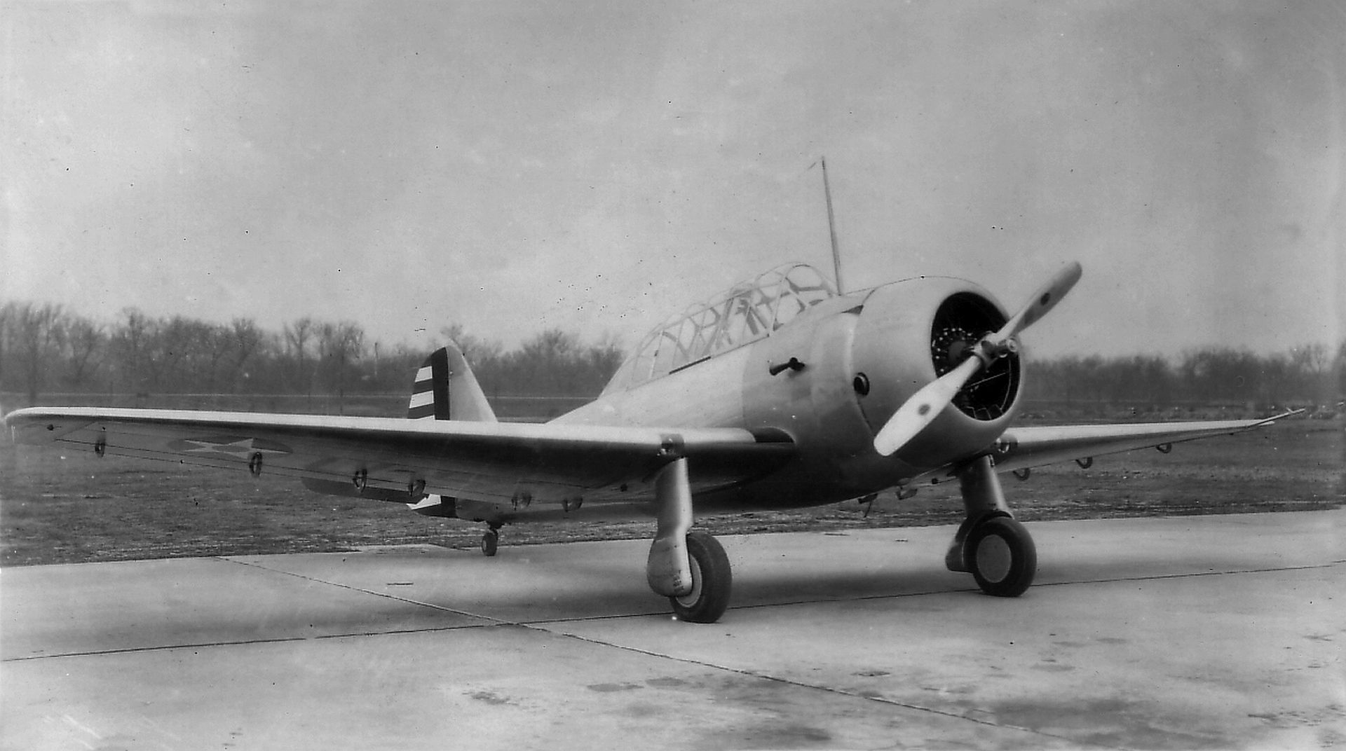
Specifications (BT-12)
General characteristics
Crew: Two (pilot and instructor)
Length: 29 ft 2 in (8.89 m)
Wingspan: 40 ft (12 m)
Height: 11 ft 4 in (3.45 m)
Wing area: 240.4 sq ft (22.33 m2)
Empty weight: 3,173 lb (1,439 kg)
Gross weight: 4,497 lb (2,040 kg)
Powerplant: 1 × Pratt & Whitney R-985-AN-1 Wasp Junior radial engine, 450 hp (340 kW)
Performance
Maximum speed: 195 mph (314 km/h, 169 kn)
Cruise speed: 150 mph (240 km/h, 130 kn)
Range: 675 mi (1,086 km, 587 nmi)
Service ceiling: 23,800 ft (7,300 m)
Time to altitude: 10 minutes to 10,000 feet
Post a reply
- Go to Previous topic
- Go to Next topic
- Go to Welcome
- Go to Introduce Yourself
- Go to General Discussion
- Go to Screenshots, Images and Videos
- Go to Off topic
- Go to Works in Progress
- Go to Skinning Tips / Tutorials
- Go to Skin Requests
- Go to IJAAF Library
- Go to Luftwaffe Library
- Go to RAF Library
- Go to USAAF / USN Library
- Go to Misc Library
- Go to The Ops Room
- Go to Made in Germany
- Go to Campaigns and Missions
- Go to Works in Progress
- Go to Juri's Air-Raid Shelter
- Go to Campaigns and Missions
- Go to Works in Progress
- Go to Skinpacks
- Go to External Projects Discussion
- Go to Books & Resources
